
產(chǎn)品中心
美國(guó)強(qiáng)鹿柴油機(jī)維修配件技術(shù)中心
約翰迪爾John Deere柴油機(jī)配件 美國(guó)麥克福斯
卡特彼勒柴油發(fā)動(dòng)機(jī)參數(shù)
沃爾沃發(fā)動(dòng)機(jī)全系參數(shù)
英國(guó)珀金斯原廠配件
珀金斯柴油機(jī)技術(shù)中心
珀金斯發(fā)動(dòng)機(jī)零件查詢圖冊(cè)
日本三菱柴油機(jī)發(fā)電機(jī)配件
德國(guó)道依茨 韓國(guó)大宇柴油發(fā)動(dòng)機(jī)配件
康明斯全系列柴油發(fā)動(dòng)機(jī)
沃爾沃 MTU 原廠配件銷售中心
瑞典沃爾沃遍達(dá)原裝柴油機(jī)配件
康明斯維修技術(shù)中心
卡特彼勒柴油發(fā)動(dòng)機(jī)原廠配件銷售中心
品牌柴油發(fā)電機(jī)組
康明斯柴油發(fā)動(dòng)機(jī)配件中心
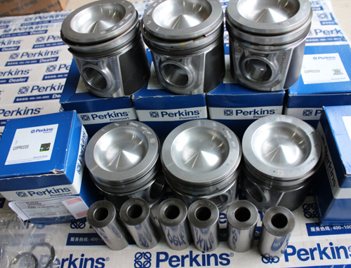
Perkins珀金斯900 3.152柴油發(fā)動(dòng)機(jī)U5PR0002活塞
詳細(xì)描述
項(xiàng)目 零配件號(hào)碼 最新件號(hào) 描述
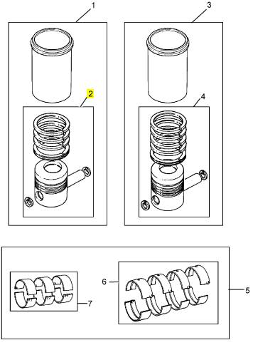
2 U5PR0002 1 檢查歷史 活塞及圈總成
|
Disassembly and Assembly Section |
|
i02754786 |
|
Engine Oil Pump - Remove |
|
Removal Procedure |
|
NOTICE |
|
Care must be taken to ensure that fluids are contained during performance of inspection, maintenance, test- ing, adjusting and repair of the product. Be prepared to collect the fluid with suitable containers before open- ing any compartment or disassembling any compo- nent containing fluids. |
|
g01385694 |
|
Illustration 66 |
|
Dispose of all fluids according to local regulations and mandates. |
|
NOTICE Keep all parts clean from contaminants. |
|
Contaminants may cause rapid wear and shortened component life. |
|
1. Drain the coolant from the cooling system into a suitable container for storage or for disposal. Refer to Operation and Maintenance Manual, “Cooling System Coolant - Change”. |
|
g01385651 |
|
Illustration 67 |
|
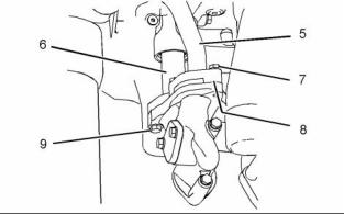
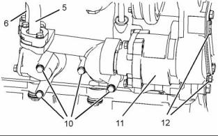
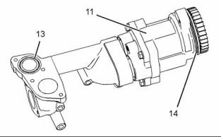
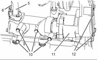
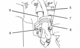
4. Remove bolts (7) and disconnect tube assembly (5) from engine oil pump (11). Remove O-ring seal (8) (not shown) from tube assembly (5). |
|
5. Remove bolts (9) and disconnect tube assembly (6) from engine oil pump (11). |
|
6. Remove bolts (10). |
|
7. Remove bolts (12). |
|
8. Remove engine oil pump (11). |
|
g01385650 |
|
Illustration 65 |
|
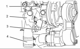
2. Loosen the hose clamps and disconnect hose (4) from connection (2). |
|
3. Remove bolts (1). Remove connection (2) from the water pump. Remove O-ring seal (3) (not shown) from the water pump. |
|
g01386064 |
|
Illustration 68 |
|
This document has been printed from SPI². Not for Resale |
![]()
![]()
![]()
![]()
![]()
![]()

![]()
![]()
![]()
|
KENR6906 |
|
33 Disassembly and Assembly Section |
|
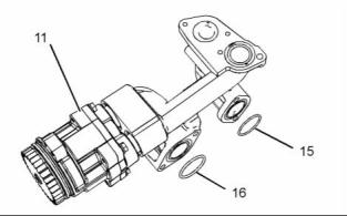
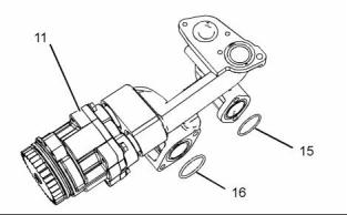
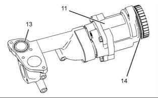
9. Remove O-ring seals (13) and (14) from engine oil pump (11). |
|
g01391548 |
|
Illustration 69 |
|
10. Remove O-ring seals (15) and (16) from engine oil pump (11). |
|
g01395753 |
|
Illustration 70 |
|
i02754790 |
|
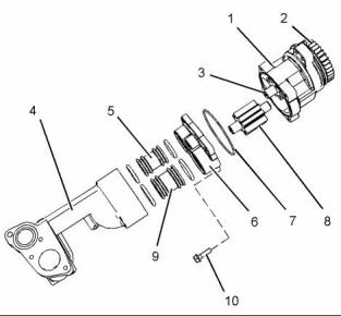
1. Remove manifold (4). |
|
Engine Oil Pump - Disassemble |
|
2. Remove tube assemblies (5) and (9). |
|
3. Remove the O-ring seals from tube assemblies |
|
(5) and (9). |
|
Disassembly Procedure |
|
4. Use Tooling (A) in order to remove gear (2). 5. Remove bolts (10). |
|
Table 15 |
|
Required Tools Part |
|
6. Remove cover (6) from engine oil pump (1). |
|
Tool |
|
Number |
|
Part Description |
|
Qty |
|
A |
|
- |
|
Puller |
|
1 |
|
7. Remove shaft assembly (3) and shaft assembly |
|
(8) from engine oil pump (1). |
|
Start By: |
|
8. Remove oil seal (7). |
|
a. Remove the engine oil pump. Refer to |
|
Disassembly and Assembly, “Engine Oil Pump - Remove”. |
|
i02754791 |
|
Engine Oil Pump - Assemble |
|
Assembly Procedure |
|
Table 16 |
|
Required Tools |
|
Tool |
|
Part Number |
|
Part Description |
|
Qty |
|
POWERPART Rubber Grease |
|
A |
|
21820221 |
|
1 |
|
1. Ensure that all components of the engine oil pump are clean and free from wear or damage. Refer to the Specifications, “Engine Oil Pump” for more information. |
|
This document has been printed from SPI². Not for Resale |
![]()
![]()

![]()

|
34 |
|
KENR6906 |
|
Disassembly and Assembly Section |
|
8. Install new O-ring seals to tube assemblies (5) and (9). Lubricate the O-ring seals with Tooling (A). |
|
9. Install tube assemblies (5) and (9) to cover (6). |
|
10. Install manifold (4) onto tube assemblies (5) and (9). |
|
End By: |
|
a. Install the engine oil pump. Refer to Disassembly and Assembly, “Engine Oil Pump - Install”. |
|
i02754792 |
|
Engine Oil Pump - Install |
|
Installation Procedure |
|
g01395753 |
|
Illustration 71 |
|
Table 17 |
|
Required Tools |
|
Tool |
|
Part Number |
|
Part Description |
|
Qty |
|
POWERPART Rubber Grease |
|
A |
|
218200221 |
|
1 |
|
NOTICE Keep all parts clean from contaminants. |
|
Contaminants may cause rapid wear and shortened component life. |
|
g01146945 |
|
Illustration 72 |
|
2. Lubricate shaft assemblies (3) and (8) with clean engine oil. Install the shaft assemblies into engine oil pump (1). |
|
3. Install a new oil seal (7) to engine oil pump (1). |
|
4. Position cover (6) onto engine oil pump (1) and install bolts (10). |
|
5. Tighten bolts (10) to a torque of 28 N·m (21 lb ft). |
|
g01391548 |
|
Illustration 73 |
|
Always wear protective gloves when handling parts that have been heated. |
|
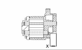
6. Heat gear (2) to a temperature of 316 °C (600 °F). |
|
7. Install gear (2) to shaft assembly (3). Ensure that Dimension (X) is 29.40 ± 0.50 mm (1.158 ± 0.020 inch). |
|
This document has been printed from SPI². Not for Resale |
![]()
![]()

![]()
![]()
![]()

![]()
![]()
![]()
|
KENR6906 |
|
35 Disassembly and Assembly Section |
|
6. Install new O-ring seal (8) (not shown) to tube assembly (5). Connect the tube assembly to engine oil pump (11) and install bolts (7). |
|
7. Tighten bolts (7) and bolt (9) to a torque of 28 N·m (21 lb ft). |
|
g01386064 |
|
Illustration 74 |
|
1. Install new O-ring seal (14) to engine oil pump (11). Lubricate the O-ring seal with Tooling (A). |
|
2. Install new O-ring seals (13), (15) and (16) to |
|
engine oil pump (11). |
|
g01385650 |
|
Illustration 77 |
|
8. Install a new O-ring seal (3) (not shown) to the water pump. position connection (2) and install bolts (1). Tighten the bolts to a torque of 28 N·m (21 lb ft). |
|
9. Connect hose (4) to connection (2). Tighten the hose clamps securely. |
|
10. Fill the cooling system. Refer to Operation and Maintenance Manual, “Cooling System Coolant - Change”. |
|
i02754793 |
|
g01385651 |
|
Illustration 75 |
|
Water Pump - Remove |
|
Removal Procedure |
|
Start By: |
|
a. Remove the front plate and the support bracket. Refer to Disassembly and Assembly, “Front Plate - Remove” |
|
NOTICE Keep all parts clean from contaminants. |
|
g01385694 |
|
Illustration 76 |
|
Contaminants may cause rapid wear and shortened component life. |
|
3. Position engine oil pump (11) and install bolts (12) finger tight. |
|
4. Install bolts (10). Tighten bolts (10) and (12) to a torque of 28 N·m (21 lb ft). |
|
5. Connect tube assembly (6) to engine oil pump (11) and install bolts (9). |
|
This document has been printed from SPI². Not for Resale |
![]()
![]()
![]()
![]()
![]()
![]()
![]()
