
產(chǎn)品中心
美國(guó)強(qiáng)鹿柴油機(jī)維修配件技術(shù)中心
約翰迪爾John Deere柴油機(jī)配件 美國(guó)麥克福斯
卡特彼勒柴油發(fā)動(dòng)機(jī)參數(shù)
沃爾沃發(fā)動(dòng)機(jī)全系參數(shù)
英國(guó)珀金斯原廠配件
珀金斯柴油機(jī)技術(shù)中心
珀金斯發(fā)動(dòng)機(jī)零件查詢圖冊(cè)
日本三菱柴油機(jī)發(fā)電機(jī)配件
德國(guó)道依茨 韓國(guó)大宇柴油發(fā)動(dòng)機(jī)配件
康明斯全系列柴油發(fā)動(dòng)機(jī)
沃爾沃 MTU 原廠配件銷售中心
瑞典沃爾沃遍達(dá)原裝柴油機(jī)配件
康明斯維修技術(shù)中心
卡特彼勒柴油發(fā)動(dòng)機(jī)原廠配件銷售中心
品牌柴油發(fā)電機(jī)組
康明斯柴油發(fā)動(dòng)機(jī)配件中心
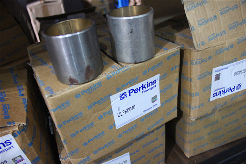
Perkins珀金斯1306-E87TA86柴油發(fā)動(dòng)機(jī)680117 C3凸輪軸襯套、1827078 C2曲軸軸承
詳細(xì)描述
項(xiàng)目 零配件號(hào)碼 新件號(hào) 描述
2 1 臺(tái)
3 1 帽
4 1 帽
5 1827078 C2 1 1827078 C2 曲軸軸承螺拴
5 1827078 C1 1 1827078 C2 螺拴
6 680117 C3 1 680117 C3 凸輪軸襯套
11 682444 C3 1 682444 C3 密封 -凸輪軸
11 682444 C1 1 682444 C3 密封 -凸輪軸
12 1830360 C1 12 1830360 C1 噴射臺(tái)
12 1830360 C1 1 1830360 C1 噴射臺(tái)
13 684902 C1 1 684902 C1 合釘
14 680484 C1 1 680484 C1 合釘
15 680483 C1 1 680483 C1 合釘
16 40005 R1 1 40005 R1 栓塞
17 40005 R1 1 40005 R1 栓塞
18 23623 R1 1 23623 R1 栓塞
19 23623 R1 1 23623 R1 栓塞
20 23623 R1 1 23623 R1 栓塞
21 444618 1 444618 栓塞
22 444612 1 444613 栓塞
23 1826342 C1 1 1826342 C1I 栓塞
24 1838845 C1 1 1838845 C1 栓塞
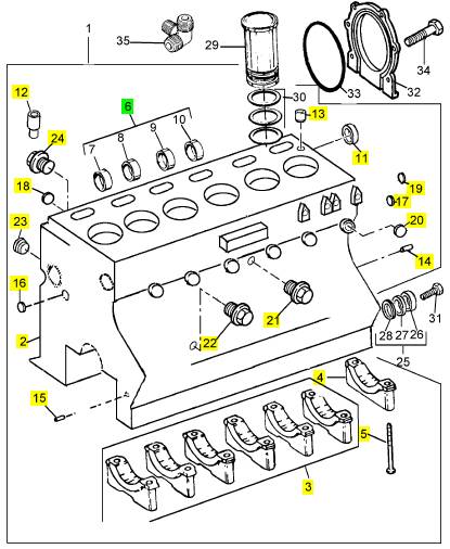
項(xiàng)目 零配件號(hào)碼 新件號(hào) 描述
2 1 臺(tái)
3 6 帽
4 1 帽
5 1827078 C1 14 1827078 C2 螺拴
12 1830360 C1 12 1830360 C1 噴射臺(tái)
13 684902 C1 2 684902 C1 合釘
14 680484 C1 2 680484 C1 合釘
15 680483 C1 2 680483 C1 合釘
17 40005 R1 2 40005 R1 栓塞
18 23623 R1 2 23623 R1 栓塞
20 23623 R1 6 23623 R1 栓塞
23 1826342 C1 7 1826342 C1I 栓塞
24 1823283 C1 1 1823283 C1 螺拴
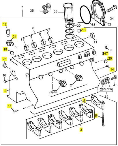
項(xiàng)目 零配件號(hào)碼 新件號(hào) 描述
2 1 臺(tái)
3 1 帽
4 1 帽
5 1827078 C2 1 1827078 C2 曲軸軸承螺拴
5 1827078 C1 1 1827078 C2 螺拴
6 680117 C3 1 680117 C3 凸輪軸襯套
11 682444 C3 1 682444 C3 密封 -凸輪軸
11 682444 C1 1 682444 C3 密封 -凸輪軸
12 1830360 C1 12 1830360 C1 噴射臺(tái)
12 1830360 C1 1 1830360 C1 噴射臺(tái)
13 684902 C1 1 684902 C1 合釘
14 680484 C1 1 680484 C1 合釘
15 680483 C1 1 680483 C1 合釘
16 40005 R1 1 40005 R1 栓塞
17 40005 R1 1 40005 R1 栓塞
18 23623 R1 1 23623 R1 栓塞
19 23623 R1 1 23623 R1 栓塞
20 23623 R1 1 23623 R1 栓塞
21 444618 1 444618 栓塞
22 444612 1 444613 栓塞
23 1826342 C1 1 1826342 C1I 栓塞
24 1838845 C1 1 1838845 C1 栓塞
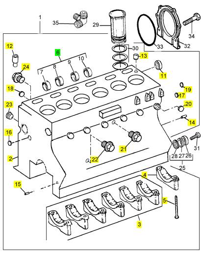
項(xiàng)目 零配件號(hào)碼 新件號(hào) 描述
2 1 臺(tái)
3 1 帽
4 1 帽
5 1827078 C2 1 1827078 C2 曲軸軸承螺拴
5 1827078 C1 1 1827078 C2 螺拴
6 680117 C3 1 680117 C3 凸輪軸襯套
11 682444 C3 1 682444 C3 密封 -凸輪軸
11 682444 C1 1 682444 C3 密封 -凸輪軸
12 1830360 C1 12 1830360 C1 噴射臺(tái)
12 1830360 C1 1 1830360 C1 噴射臺(tái)
13 684902 C1 1 684902 C1 合釘
14 680484 C1 1 680484 C1 合釘
15 680483 C1 1 680483 C1 合釘
16 40005 R1 1 40005 R1 栓塞
17 40005 R1 1 40005 R1 栓塞
18 23623 R1 1 23623 R1 栓塞
19 23623 R1 1 23623 R1 栓塞
20 23623 R1 1 23623 R1 栓塞
21 444618 1 444618 栓塞
22 444612 1 444613 栓塞
23 1826342 C1 1 1826342 C1I 栓塞
24 1838845 C1 1 1838845 C1 栓塞
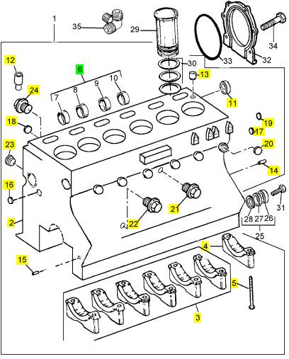
項(xiàng)目 零配件號(hào)碼 新件號(hào) 描述
2 1 臺(tái)
3 1 帽
4 1 帽
5 1827078 C2 1 1827078 C2 曲軸軸承螺拴
5 1827078 C1 1 1827078 C2 螺拴
6 680117 C3 1 680117 C3 凸輪軸襯套
11 682444 C3 1 682444 C3 密封 -凸輪軸
11 682444 C1 1 682444 C3 密封 -凸輪軸
12 1830360 C1 12 1830360 C1 噴射臺(tái)
12 1830360 C1 1 1830360 C1 噴射臺(tái)
13 684902 C1 1 684902 C1 合釘
14 680484 C1 1 680484 C1 合釘
15 680483 C1 1 680483 C1 合釘
16 40005 R1 1 40005 R1 栓塞
17 40005 R1 1 40005 R1 栓塞
18 23623 R1 1 23623 R1 栓塞
19 23623 R1 1 23623 R1 栓塞
20 23623 R1 1 23623 R1 栓塞
21 444618 1 444618 栓塞
22 444612 1 444613 栓塞
23 1826342 C1 1 1826342 C1I 栓塞
24 1838845 C1 1 1838845 C1 栓塞
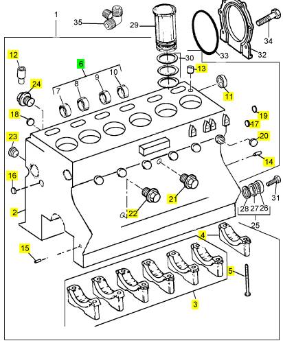
|
Peregrine EDi and 1300 Series EDi |
|
Turbocharger faults |
|
The chart below is given to assist in the correct diagnosis of turbocharger faults. |
|
Problems |
|
Possible causes, code numbers 1, 4, 5, 6, 7, 8, 9, 10, 11, 18, 20, 21, 22, 25, 26, 27, 28, 34, |
|
Not enough power |
|
35, 36 |
|
1, 4, 5, 6, 7, 8, 9, 10, 11, 18, 20, 21, 22, 25, 26, 27, 28, 34, 35, 36 |
|
Black smoke Blue smoke |
|
1, 2, 4, 6, 8, 9, 17, 19, 20, 21, 22, 30, 31, 32, 34 2, 8, 15, 17, 19, 20, 28, 29, 31, 32, 34 2, 7, 8, 17, 19, 20, 22, 28, 30, 31, 32 1, 2, 4, 5, 6, 8, 19, 20, 21, 28, 31, 32 8, 12, 14, 15, 16, 23, 24, 29, 32, 33, 37, 38 2, 7, 17, 18, 19, 20, 22, 28, 31, 32 |
|
High consumption of lubricating oil Too much lubricating oil at the turbine end Too much lubricating oil at the compressor end Not enough lubrication |
|
Lubricating oil in the exhaust manifold |
|
1, 2, 3, 4, 5, 6, 8, 10, 11, 17, 18, 19, 20, 21, 28, 32, 34, 39, 40 |
|
Inside of the induction manifold wet Damaged compressor impeller Damaged turbine rotor |
|
3, 4, 6, 8, 12, 15, 16, 20, 21, 23, 24, 29, 32, 33, 37, 38 |
|
7, 8, 12, 13, 14, 15, 16, 18, 20, 22, 23, 24, 25, 27, 29, 32, 33, 37, 38 |
|
3, 6, 7, 8, 12, 13, 14, 15, 16, 18, 20, 22, 23, 24, 29, 32, 33, 37, 38 |
|
Rotating assembly does not turn freely Worn bearings, bearing bores or journals Noise from the turbocharger |
|
6, 7, 8, 12, 13, 14, 15, 16, 23, 24, 29, 33, 37, 38 |
|
1, 3, 4, 5, 6, 7, 8, 9, 10, 11, 12, 13, 14, 15, 16, 18, 20, 21, 22, 23, 24, 29, 32, 33, 34, 37, 38, |
|
Sludge or carbon deposit in the bearing housing |
|
2, 11, 13, 14, 15, 17, 18, 24, 29, 33, 37, 38 |
|
Workshop Manual, TPD 1353E, Issue 3 |
|
125 |
|
This document has been printed from SPI². Not for Resale |
![]()
![]()

|
9 |
|
Peregrine EDi and 1300 Series EDi |
|
List of possible causes |
|
1 Element of the air filter dirty 2 Restricted crankcase breather |
|
3 Element of the air filter missing, leaking or not sealing correctly. Loose connection to turbocharger. 4 Internal distortion or restriction in pipe from air filter to turbocharger. 5 Damaged / restricted crossover pipe, turbocharger to induction manifold. 6 Restriction between air filter and turbocharger. 7 Restriction in exhaust system. |
|
8 Turbocharger loose or clamps / setscrews loose. 9 Induction manifold cracked or loose, flanges distorted. 10 Exhaust manifold cracked or loose, flanges distorted. 11 Restricted exhaust system. |
|
12 Delay of lubricating oil to turbocharger at engine start. 13 Insufficient lubrication. |
|
14 Dirty lubricating oil. |
|
15 Incorrect lubricating oil. |
|
16 Restricted lubricating oil supply pipe. 17 Restricted lubricating oil drain pipe. |
|
18 Turbine housing damaged or restricted. 19 Leakage from turbocharger seals. |
|
20 Worn turbocharger bearings. |
|
21 Excessive dirt in compressor housing. 22 Excessive carbon behind turbine rotor. 23 Engine speed raised too rapidly at initial start. 24 Insufficient engine idle period. |
|
25 Faulty fuel injection pump. |
|
26 Worn or damaged atomisers. |
|
27 Valves burned. |
|
28 Worn piston rings. |
|
29 Lubricating oil leakage from supply pipe. 30 Excessive preservation fluid (on initial engine start). 31 Excessive engine idle period. |
|
32 Restriction in turbocharger bearing housing. 33 Restriction in lubricating oil filter. |
|
34 Wet type air cleaner: Restricted, dirty element, viscosity of oil too low / high. 35 Waste-gate actuator faulty or damaged. 36 Waste-gate valve not free. |
|
37 Engine stopped too soon from high load. 38 Insufficient lubricating oil. |
|
39 Fuel leakage from fuelled starting aid. 40 Crack in backplate of compressor. |
|
126 |
|
Workshop Manual, TPD 1353E, Issue 3 |
|
This document has been printed from SPI². Not for Resale |
![]()
![]()
|
Peregrine EDi and 1300 Series EDi |
|
10 |
|
Lubrication system |
|
10 |
|
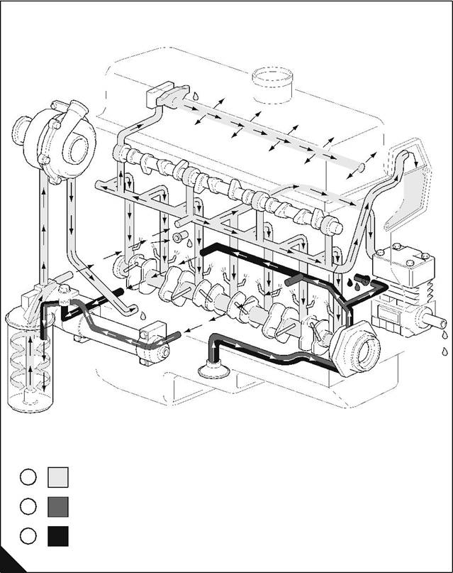
General description (Low-pressure system) |
|
Refer to "Low-pressure system flow diagram" on page 128 for illustration references. |
|
Lubricating oil from the sump passes through a strainer and a pipe into a channel in the timing case. The lubricating oil passes through the channel to the inlet of the oil pump. |
|
The lubricating oil passes from the oil pump, under pressure, through a channel in the timing case. The oil either passes through a relief valve which is fitted in the timing case or passes into an oil pressure rail. The |
|
2 |
|
2 |
|
relief valve opens at 551 kPa (80 lbf/in ) 5,6 kgf/cm and returns the oil to the sump. |
|
A temperature control valve in the oil filter head controls the flow of oil from the pressure rail. If the oil is hot (A2), the valve will open and the oil passes through the oil cooler to the oil filter head and then into the filter. If the oil is cold (A3), the valve closes and the oil passes directly to the oil filter. |
|
2 |
|
Clean lubricating oil (A1) passes from the filter to a regulator valve which operates at 331 kPa (48 lbf/in ) |
|
2 |
|
3,37 kgf/cm . If a restriction occurs in the filter element, a by-pass valve fitted in the filter housing opens. Oil |
|
that by-passes the filter passes directly to the regulator valve. The regulator valve either by-passes oil to the sump or allows oil to pass to the main pressure rail and then through ports in the cylinder block to the crankshaft main journals. |
|
Lubricating oil from the main pressure rail also passes: |
|
l To jets in the crankcase that spray oil on the underside of the pistons to cool them. l Through a channel in the crankcase and in the timing case to the reservoir for the high-pressure pump. There are ports in the crankcase through which oil passes to the camshaft journals. |
|
Lubricating oil passes through holes drilled in the crankshaft journals to the crank pins to lubricate the big end bearings. |
|
Lubricating oil from the rear journal of the crankshaft passes to the rear of the rocker shaft. The oil passes along the hollow rocker shaft to lubricate the rocker levers. |
|
The turbocharger receives clean oil through a pipe from the oil filter head. The oil passes through the bearing housing of the turbocharger and returns through a pipe to the crankcase, and then to the sump. |
|
The compressor, if fitted, receives oil from a union connection fitted to the cylinder block. Lubricating oil from the main pressure rail passes through a drilled hole to the union, the oil then passes to the compressor. Lubricating oil from the compressor returns to the sump. |
|
Workshop Manual, TPD 1353E, Issue 3 |
|
127 |
|
This document has been printed from SPI². Not for Resale |
![]()
![]()
|
10 |
|
Peregrine EDi and 1300 Series EDi |
|
Low-pressure system flow diagram |
|
A1 Filtered oil |
|
A2 Hot oil |
|
A3 Cold oil |
|
1 2 |
|
3 |
|
A |
|
W201 |
|
128 |
|
Workshop Manual, TPD 1353E, Issue 3 |
|
This document has been printed from SPI². Not for Resale |
![]()
![]()
|
10 |
|
Peregrine EDi and 1300 Series EDi |
|
Filter canister |
|
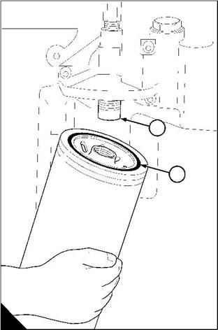
To renew the canister of the lubricating oil filter |
|
Operation 10-1 |
|
Warning! Discard the used canister and lubricating oil in a safe place and in accordance with local regulations. Caution: Ensure that the application is on a level surface to ensure an accurate reading on the dipstick. |
|
1 Operate the engine before the oil filter is removed. This ensures that oil is in the bearing housing of the turbocharger. |
|
2 Put a tray under the filter to retain lubricating oil. |
|
3 Clean thoroughly the outer surfaces of the filter assembly. |
|
4 Use a strap wrench or similar tool to loosen the filter canister, remove and discard the canister. Ensure that the adaptor (A1) is secure in the filter head. |
|
Warning! Discard the used canister and lubricating oil in a safe place and in accordance with local regulations. |
|
5 Clean inside the filter head. |
|
6 Lubricate the seal (A2) on top of the new canister with clean engine lubricating oil. |
|
7 Fit the new canister and tighten by hand until the seal contacts the filter head. Tighten the canister a further |
|
1/ to / of a turn by hand. Do not use a strap wrench. |
|
3 |
|
2 |
|
4 |
|
8 Ensure that there is lubricating oil in the sump. |
|
1 |
|
2 |
|
A |
|
W014 |
|
Continued |
|
Workshop Manual, TPD 1353E, Issue 3 |
|
129 |
|
This document has been printed from SPI². Not for Resale |
![]()
![]()
![]()
![]()
|
10 |
|
Peregrine EDi and 1300 Series EDi |
|
9 Turn the start key to the ‘ON’ position and start the engine. |
|
Note: The engine will not start and operate until oil pressure is obtained. Oil pressure is indicated when the warning light is extinguished or by a reading on the gauge. |
|
Caution: Do not fill the sump past the ‘FULL’ mark on the dipstick. |
|
10 When the engine starts check for leakage from the filter. Stop the engine. After 15 minutes check the oil level on the dipstick and, if necessary, put more lubricating oil into the sump. |
|
130 |
|
Workshop Manual, TPD 1353E, Issue 3 |
|
This document has been printed from SPI². Not for Resale |
![]()
![]()
|
10 |
|
Peregrine EDi and 1300 Series EDi |
|
Oil filter head and cooler assembly |
|
To remove |
|
Operation 10-2 |
|
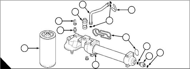
Note: The casting for the oil filter head includes the rear end-casing for the oil cooler (A7) and houses the oil temperature control valve. The oil filter head and the oil cooler are an assembly. |
|
1 Drain the engine lubricating oil. 2 Drain the cooling system. |
|
1 |
|
3 |
|
11 |
|
10 |
|
2 |
|
9 |
|
4 |
|
6 |
|
8 |
|
6 |
|
5 |
|
A |
|
7 |
|
W059 |
|
3 Remove the lubricating oil canister (A8), see Operation 10-1. 4 Disconnect the oil supply pipe (A10) for the turbocharger. |
|
5 Remove the setscrew from the clamp (A3) for the coolant inlet pipe (A1). |
|
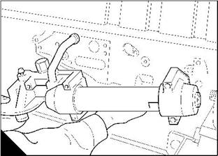
6 Release the setscrews and remove the oil filter head and cooler assembly (B) from the cylinder block. 7 Discard the joints (A4) from the filter head and discard the ’O’ rings (A2) from the coolant inlet pipe. 8 Remove the coolant outlet pipe (A5) and discard the ’O’ rings (A6) from the coolant outlet pipe. |
|
B |
|
W124 |
|
Workshop Manual, TPD 1353E, Issue 3 |
|
131 |
|
This document has been printed from SPI². Not for Resale |
![]()
![]()
![]()
![]()
|
10 |
|
Peregrine EDi and 1300 Series EDi |
|
To fit |
|
Operation 10-3 |
|
Special requirements |
|
Consumable products |
|
Description |
|
Part number |
|
21820117 or 21820118 |
|
POWERPART Threadlock and nutlock |
|
1 Clean the outside of the oil filter head and cooler assembly (A7). Clean the joint face on the cylinder block, the coolant inlet pipe (A1) and coolant outlet pipe (A5). |
|
2 Fit new joints (A4) to the filter head and fit new ’O’ rings (A2 and A6) to the coolant inlet and outlet pipes. |
|
1 |
|
3 |
|
11 |
|
10 |
|
2 |
|
9 |
|
4 |
|
6 |
|
8 |
|
6 |
|
5 |
|
A |
|
7 |
|
W059 |
|
3 Put the filter head and oil cooler assembly (B) in position on the cylinder block. Ensure that the coolant inlet pipe is correctly engaged in the cylinder block and in the filter head. Fit and tighten the setscrews for the filter head / oil cooler assembly. |
|
4 Fit and tighten the setscrew for the clamp (A3) of the coolant inlet pipe. |
|
5 Clean the threads of the union connection (A9) for the turbocharger pipe (A10). Apply POWERPART Threadlock and nutlock to the thread of the connection that enters the filter head. Use a separate spanner to hold the union connection while the union nut on the pipe is tightened. |
|
6 Fit a new oil filter canister (A8), see Operation 10-1. 7 Fill the cooling system to the correct level. |
|
8 Fill the sump to the correct level with lubricating oil of an approved grade, see Chapter 5 in the User’s Handbook. |
|
B |
|
W124 |
|
132 |
|
Workshop Manual, TPD 1353E, Issue 3 |
