
產(chǎn)品中心
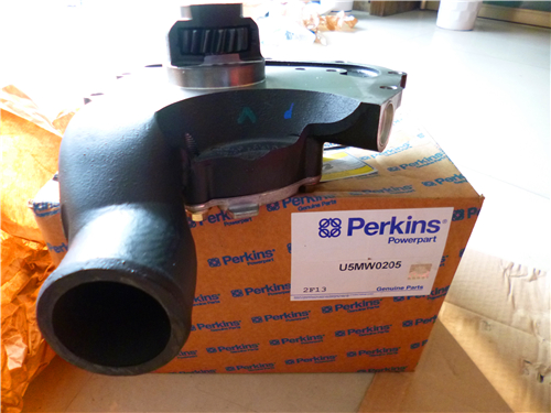
Perkins1206-E70TTA柴油發(fā)動機水泵
詳細(xì)描述
項目 零配件號碼 新件號 描述
2 1 水泵
9 T407626 1 T407626 密封墊片 - 水的泵
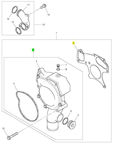
項目 零配件號碼 新件號 描述
3 1 水泵
4 T412517 1 T412517 密封墊片
5 T412535 1 T412535 栓塞
6 T412540 1 T412540 密封
7 T412539 1 T412539 栓塞
8 T412542 1 T412542 密封O型圈

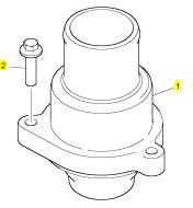
項目 零配件號碼 新件號 描述
1 T414226 1 T414226 恒溫節(jié)溫器組合
1 T409202 1 T409202 恒溫節(jié)溫器組合
2 2314 H005 3 2314 H005 螺旋
項目 零配件號碼 新件號 描述
1 T411746 1 T411746 啟動馬達(dá)
2 2313 M101 3 2313 M101 圖釘
3 2318 A605 3 2318 A605 螺帽

項目 零配件號碼 新件號 描述
1 T405773 1 T405773 凸輪軸
4 T411902 12 T411902 挺桿
4 T405810 12 T411902 挺桿
5 3142 V011 12 3142 V011 PUSHROD
5 T405746 12 3142 V011 PUSHROD

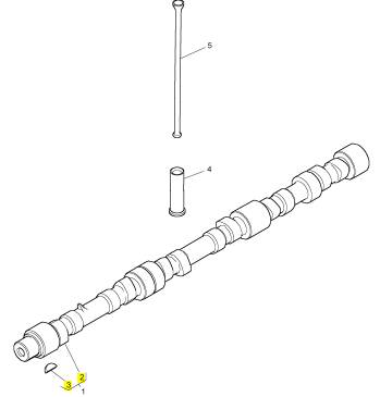
項目 零配件號碼 新件號 描述
2 1 凸輪軸
3 0500012 1 0500012 半圓鍵
|
Table 87 |
|
Diagnostic Trouble Codes for ARD Failed to Ignite Code Description |
|
J1939 Code |
|
Comments |
|
3473-31 |
|
Aftertreatment #1 Failed to Ignite |
|
The ARD has failed to ignite for a regeneration cycle or the ARD failed to ignite during an ARD Ignition Test. Usually, this code is ac- companied by another logged code that indicates the condition that caused the failure to ignite. |
|
System Operation |
|
(Table 88, contd) |
|
3487-7 |
|
Aftertreatment #1 Air Pressure Control : Not Responding Properly |
|
Motorized Valve - Test |
|
The combustion air system routes pressurized air from the outlet of the high-pressure turbocharger to the ARD. The combustion air is mixed with fuel inside the ARD combustion head. The air/fuel mixture is ignited and the air/fuel mixture is burned in order to increase the temperature of the exhaust gas. The high temperature exhaust gas burns off the soot in the Diesel Particulate Filter (DPF). This process is known as DPF regeneration. |
|
3480-16 3480-17 3480-18 |
|
Aftertreatment #1 Fuel Pressure #1 : High - Moderate Se- verity (2) |
|
ARD Pilot Fuel Pressure Is High |
|
Aftertreatment #1 Fuel Pressure #1 : Low - Least Severe (1) |
|
ARD Pilot Fuel Pressure Is Low |
|
The ECM sends a pulse width modulated signal to the combustion air valve. The actuator in the combustion air valve regulates the combustion air to the ARD combustion head. |
|
Aftertreatment #1 Fuel Pressure #1 : Low - Moderate Se- verity (2) |
|
ARD Pilot Fuel Pressure Is Low |
|
The ECM also sends pulse width modulated signals to the pilot fuel control valve. The fuel control valves regulate the amount of fuel that is injected into the ARD combustion head. |
|
102-18 3556-7 |
|
Engine Intake Mani- Intake Manifold Air Pres- sure Is Low |
|
fold #1 Pressure Low (2) |
|
The ECM controls the ARD ignition system. Whenever the ARD is required to operate, the ECM operates the ARD ignition coil which then generates high voltage pulses in the ignition cable. The high voltage pulses create sparks at the spark plug in the ARD head. The spark ignites the fuel/air mixture in the ARD. |
|
Aftertreatment Fuel ARD Nozzle - Test Injector #1 : Not Re- |
|
sponding Properly |
|
3484-5 3484-6 4265-5 |
|
Aftertreatment #1 Ignition: Current Be- low Normal |
|
ARD Ignition - Test ARD Ignition - Test ARD Ignition - Test |
|
Aftertreatment #1 Ignition : Current Above Normal |
|
If the amount of fuel or air that enters the ARD combustion head is incorrect or there are no ignition sparks, combustion may not occur. |
|
Aftertreatment #1 Transformer Secon- dary Output : Cur- rent Below Normal |
|
Test Step 1. Check for Associated Diagnostic Trouble Codes |
|
4265-6 |
|
Aftertreatment #1 Transformer Secon- dary Output : Cur- rent Above Normal |
|
ARD Ignition - Test |
|
A. Establish communication between the electronic service tool and the engine ECM. |
|
B. Table 88 lists the diagnostic trouble codes that are associated with the “3473-31 Aftertreatment #1 Failed to Ignite” code. Determine if any of the codes in Table 88 are present. |
|
Results: |
|
• An associated diagnostic trouble code is not present. Proceed to Test Step 3. |
|
Table 88 |
|
Associated Diagnostic Codes |
|
• An associated diagnostic trouble code is present. |
|
Associated Diagnostic Procedure |
|
J1939 Code |
|
Description |
|
Repair: Refer to TroubleshootingDiagnostic Trouble Codes in order to troubleshoot the associated diagnostic code. |
|
(continued) |
|
STOP. |
|
This document is printed from SPI². Not for RESALE |



![]()
|
68 |
|
KENR9101 |
|
Symptom Troubleshooting |
|
Test Step 2. Inspect the ARD Ignition System |
|
A. Visually inspect the components for the ARD ignition system. Check for the following faults: |
|
• Loose connections or damaged connectors |
|
• Moisture on the connectors or the wiring |
|
• Damage caused by excessive heat • Damage caused by chafing • Incorrect routing of wiring • Damaged insulation |
|
B. Verify that each end of the ground wire is securely connected to both ground points. |
|
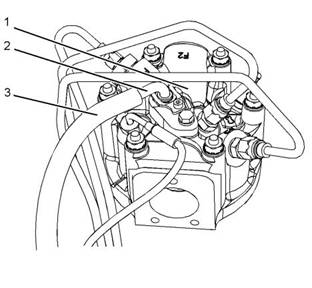
Illustration 29 |
|
g02856716 |
|
Measuring the current flow |
|
(1) ARD combustionhead (2) Metal part of heater wire (3) Insulated part of heater wire |
|
C. Push the boot on each end of the ignition wire. There should not be a “click” when you push the boot onto either part. If a “click” is felt, the clip inside the boot was not connected. |
|
B. Connect a suitable clamp-ammeter around the insulated part of the heater wire (3). Make sure that the jaws of the ammeter are away from the metal part of the heater wire (2). |
|
D. Perform a 45 N (10 lb) pull test on each harness wire at the 3-pin connector for the ignition coil. |
|
Results: |
|
C. Establish communication between the electronic service tool and the ECM. Refer to TroubleshootingElectronic Service Tools for the proper procedure. |
|
• The wiring is not OK. – There is a fault in the wiring. A wire end is not connected or a wire is damaged. Proceed to Test Step 9. |
|
• The wiring is OK. Proceed to Test Step 3. |
|
The ignition system may cause an electrical shock hazard, which may cause personal injury or death. Avoid contacting the ignition system components and the ignition system wiring dur- ing operation. |
|
Test Step 3. Check the Current Flow to the ARD Nozzle Heater |
|
A. Verify that the engine is off. |
|
D. Start the engine. Activate the “ARD Nozzle Heater Test” . |
|
E. Record the current reading on the ammeter. |
|
F. Disable the “ARD Nozzle Heater Test” . Stop the engine. Remove the clamp-ammeter. |
|
G.Disconnect the electronic service tool. |
|
Results: |
|
• The ammeter reads at least 7 Amps for a 12 VDC system or 3.5 Amps for a 24 VDC system. – The current consumption is normal. Proceed to Test Step 4. This document is printed from SPI². Not for RESALE |
![]()
![]()
![]()
![]()
![]()
|
KENR9101 |
|
69 |
|
Symptom Troubleshooting |
|
• The ammeter reads less than 7 Amps for a 12 |
|
C. Use the “ARD Ignition Transformer Primary |
|
VDC system or 3.5 Amps for a 24 VDC system. |
|
Status” override on the electronic service tool to |
|
turn on the ARD ignition system. |
|
Repair: Investigate the cause of the low current consumption. Refer to TroubleshootingARD Nozzle Heater - Test. |
|
Expected Result: The spark indicator flashes. Results: |
|
STOP. |
|
Test Step 4. Check for Voltage at the Spark Plug |
|
• The spark indicator flashes. Proceed to Test Step 5. |
|
• The spark indicator does not flash. |
|
Repair: Proceed to TroubleshootingARD Ignition - Test. |
|
STOP. |
|
Test Step 5. Clean the Components in the ARD Combustion Head |
|
Illustration30 |
|
g02856717 |
|
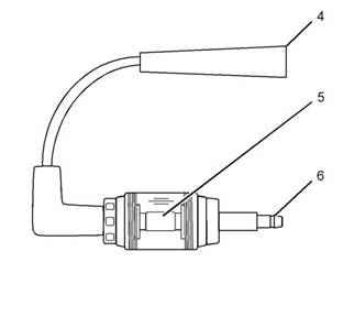
T400026 Spark Indicator |
|
(4) Connector for spark plug (5) Spark window (6) Connector for ignition wire |
|
NOTICE |
|
If the engine is running, the ARD spark plug will continue to fire. Turn the key to the OFF position before servicing the ARD spark plug. |
|
Illustration 31 |
|
g02856718 |
|
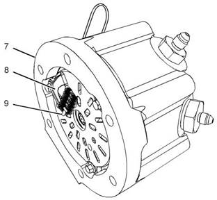
Use of the plug bore brush |
|
A. Disconnect the ignition wire from the ARD spark plug. |
|
(7) ARD combustionhead (8) Ground probe |
|
(9) 305-2389 Plug Bore Brush |
|
B. Connect the spark indicator between the ignition wire and the ARD spark plug. |
|
The ignition system may cause an electrical shock hazard, which may cause personal injury or death. Avoid contacting the ignition system components and the ignition system wiring dur- ing operation. |
|
This document is printed from SPI². Not for RESALE |
![]()
![]()
![]()
![]()
![]()
![]()
![]()
![]()
![]()
|
70 |
|
KENR9101 |
|
Symptom Troubleshooting |
|
The components are clean and the spark plug is not visibly damaged. |
|
Results: |
|
• Result 1: The components are clean and the spark plug is not visibly damaged. |
|
Repair: Perform the following procedure: |
|
A. Install the original spark plug. |
|
The ignition system may cause an electrical shock hazard, which may cause personal in- jury or death. Avoid contacting the ignition system components and the ignition system wiring during operation. |
|
B. Use the electronic service tool to perform an ARD ignition test. |
|
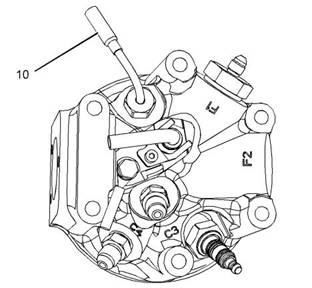
Illustration32 |
|
g02856719 |
|
(10) Flame detection temperature sensor |
|
Note: The ARD Ignition Test cannot be performed if the DPF soot loading is above 80%. When the DPF soot loading is above 80%, use the electronic service tool to perform a Manual DPF Regeneration. |
|
NOTICE |
|
If the engine is running, the ARD spark plug will continue to fire. Turn the key to the OFF position before servicing the ARD spark plug. |
|
C. Confirm that the fault has been eliminated. |
|
A. Remove the spark plug from the ARD combustion head. |
|
D. If the fault is still present, install a replacement spark plug. Refer to |
|
B. Clean ground probe (2) inside ARD combustion head (1) by running T400005 Plug Bore Brush through the hole in the ARD combustion head. Run the brush through the hole several times. Refer to Illustration 30 |
|
SpecificationsElectronic Control Wiring Group (ARD) for the correct torque value. |
|
E. Use the electronic service tool to perform an ARD ignition test. |
|
Note: The ARD Ignition Test cannot be performed if the DPF soot loading is above 80%. When the DPF soot loading is above 80%, use the electronic service tool to perform a Manual DPF Regeneration. |
|
C. Inspect the spark plug. Look for the following defects: |
|
Carbon Deposits – Use a nonmetallic cleaning pad to clean the spark plug. |
|
Bent Probe – Check the probe for damage. |
|
F. Confirm that the fault has been eliminated. Proceed to Test Step 6. |
|
Damaged Insulator – Check the insulator for damage. |
|
• Result 2: The spark plug is damaged. Repair: Perform the following procedure: |
|
Note: The spark plug may be damaged if the spark plug is dropped. Do not install a sp, ark plug that has been dropped. |
|
A. Install a replacement spark plug. Refer to SpecificationsElectronic Control Wiring Group (ARD) for the correct torque value. |
|
D. Remove flame detection temperature sensor(10). |
|
E. Clean the flame detection temperature sensor. Use a nonmetallic cleaning pad to clean the sensor. |
|
B. Use the electronic service tool to perform an ARD ignition test. |
|
F. Install the flame detection temperature sensor. |
|
Expected Result: |
|
This document is printed from SPI². Not for RESALE |
![]()
![]()
![]()
![]()
![]()
![]()
![]()
|
KENR9101 |
|
71 |
|
Symptom Troubleshooting |
|
Note: The ARD Ignition Test cannot be |
|
performed if the DPF soot loading is above 80%. When the DPF soot loading is above 80%, use the electronic service tool to perform a Manual DPF Regeneration. |
|
The ignition system may cause an electrical shock hazard, which may cause personal injury or death. Avoid contacting the ignition system components and the ignition system wiring dur- ing operation. |
|
C. Confirm that the fault has been eliminated. Proceed to Test Step 6. |
|
C. Use the electronic service tool in order to perform the “ARD Ignition Test” . |
|
Test Step 6. Check the ARD Air System |
|
Use the electronic service tool to perform the ARD Air System Service Test. |
|
Note: The ARD Ignition Test cannot be performed if the DPF soot loading is above 80%. When the DPF soot loading is above 80%, use the electronic service tool to perform a Manual DPF Regeneration. |
|
Results: |
|
• The ARD Air System Service Test is successful. |
|
Proceed to Test Step 7. |
|
Results: |
|
• The ARD Air System Service Test is failed. |
|
• The ARD ignition test was successful and no |
|
codes were logged. – Return the unit to service. |
|
Repair: Investigate the cause of the test failure. Refer to TroubleshootingARD Combustion Supply Air Pressure Is Low. |
|
STOP. |
|
• The ARD ignition test was not successful and codes were logged. Proceed to Test Step 8. |
|
STOP. |
|
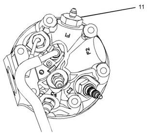
Test Step 7. Replace the ARD Filter Connector in the ARD Combustion Head |
|
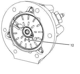
Test Step 8. Inspect ARD Swirl Plate |
|
Illustration 34 |
|
g02865416 |
|
Illustration33 |
|
g02931740 |
|
(12) Swirl plate slots |
|
ARD Combustion Head (11) ARD pilot filter connector |
|
A. Remove the ARD head. Refer to Disassembly and AssemblyCombustion Head Group (ARD) - Remove and Install - Clean Emissions Module for the proper procedure to remove the ARD combustion head. |
|
A. Replace pilot filter connector (11) in the ARD combustion head. Refer to Illustration 33 . |
|
B. Clear all diagnostic codes. |
|
This document is printed from SPI². Not for RESALE |
![]()
![]()
![]()
![]()
![]()
![]()
![]()
|
72 |
|
KENR9101 |
|
Symptom Troubleshooting |
|
Note: Soot accumulation is normal. Slot fouling is defined as more than 1/2 the inner row slots being 100 percent blocked. Partially blocked inner row slots are normal and do not affect regeneration performance. Refer to Illustration 34 . |
|
A. Clear all diagnostic codes. |
|
B. Click the “Disconnect” icon on the electronic service tool in order to disconnect the electronic service tool from the engine. |
|
B. Inspect the swirl plate for fouled slots (12). Results: |
|
C. Turn the keyswitch to the OFF position. Wait for 5 seconds. |
|
D. Turn the keyswitch to the ON position. |
|
• The swirl plate is fouled. |
|
E. Click the “Connect” icon on the electronic service |
|
Repair: Perform the following procedure: |
|
tool. |
|
A. Clean the swirl plate. Refer to Testing and AdjustingSwirl Plate (ARD Combustion) - Inspect/Clean. |
|
F. Start the engine. Allow the engine to idle for 3 minutes. |
|
Note: Do not use the operators switch for a stationary regeneration. The service tests provide enhanced diagnostics that are necessary for proper troubleshooting and repair. |
|
B. Install the ARD head. Refer to Disassembly and AssemblyCombustion Head Group (ARD) - Remove and Install - Clean Emissions Module. |
|
G.Start a “Manual DPF Regeneration” in the |
|
electronic service tool. |
|
C. Reset all active codes and clear all logged codes. Use the electronic service tool to perform the “ARD Ignition Test” and verify that there are no fuel leaks. |
|
Note: The ECM tests the nozzles for plugging after the “Manual DPF Regeneration” is complete. Approximately 10 minutes are required in order for the test to provide a result. A code will become active if the nozzles are plugged. |
|
Note: The ARD Ignition Test cannot be performed if the DPF soot loading is above 80%. When the DPF soot loading is above 80%, use the electronic service tool to perform a Manual DPF Regeneration. |
|
Results: |
|
• The “Manual DPF Regeneration” completed successfully. There are no additional codes. – The system is operating correctly. |
|
Proceed to Test Step 9. |
|
• The swirl plate is not fouled. Repair: Perform the following procedure: |
|
STOP. STOP |
|
• The “Manual DPF Regeneration” did not complete successfully. There are additional diagnostic codes. |
|
A. Replace the ARD combustion head. Refer to Disassembly and AssemblyCombustion Head Group (ARD) - Remove and Install. |
|
Repair: Troubleshoot the additional diagnostic codes before returning the unit to service. Refer to Troubleshooting for the correct procedure. |
|
B. Reset all active codes and clear all logged codes. Use the electronic service tool to perform the “ARD Ignition Test” and verify that there are no fuel leaks. |
|
Verify that the fault has been eliminated. |
|
Note: The ARD Ignition Test cannot be performed if the DPF soot loading is above 80%. When the DPF soot loading is above 80%, use the electronic service tool to perform a Manual DPF Regeneration. |
|
STOP. |
|
i03771773 |
|
ARD Is Disabled |
|
Proceed to Test Step 9. |
|
Use this procedure in order to troubleshoot a failed Diesel Particulate Filter (DPF) regeneration. Use this procedure if one of the following diagnostic trouble codes are active. |
|
Test Step 9. Perform a Manual DPF Regeneration |
|
Note: This test must be performed through the electronic service tool. The electronic service tool enhances the diagnostics during the service test. |
|
This document is printed from SPI². Not for RESALE |
