產(chǎn)品中心
美國(guó)強(qiáng)鹿柴油機(jī)維修配件技術(shù)中心
約翰迪爾John Deere柴油機(jī)配件 美國(guó)麥克福斯
卡特彼勒柴油發(fā)動(dòng)機(jī)參數(shù)
沃爾沃發(fā)動(dòng)機(jī)全系參數(shù)
英國(guó)珀金斯原廠配件
珀金斯柴油機(jī)技術(shù)中心
珀金斯發(fā)動(dòng)機(jī)零件查詢圖冊(cè)
日本三菱柴油機(jī)發(fā)電機(jī)配件
德國(guó)道依茨 韓國(guó)大宇柴油發(fā)動(dòng)機(jī)配件
康明斯全系列柴油發(fā)動(dòng)機(jī)
沃爾沃 MTU 原廠配件銷售中心
瑞典沃爾沃遍達(dá)原裝柴油機(jī)配件
康明斯維修技術(shù)中心
卡特彼勒柴油發(fā)動(dòng)機(jī)原廠配件銷售中心
品牌柴油發(fā)電機(jī)組
康明斯柴油發(fā)動(dòng)機(jī)配件中心

Perkins3012柴油發(fā)動(dòng)機(jī)威爾遜P850E柴油發(fā)電機(jī)配件高壓油泵
詳細(xì)描述
項(xiàng)目 零配件號(hào)碼 最近的部分號(hào)碼 描述
CV11445/35 Z 1 CV1445/35 R 高壓油泵
CV11445/35 1 CV1445/35 R 高壓油泵
() CV11445/35 R 1 CV1445/35 R 高壓油泵

項(xiàng)目 零配件號(hào)碼 最近的部分號(hào)碼 描述
ST46004 3 ST46004 套筒
ST46007 2 ST46007 套筒
ST46029 3 ST46029 螺帽
ST46032 2 ST46032 螺帽
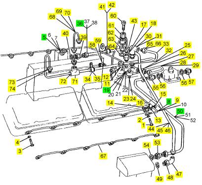
1 CV1687 1 CV1687 油管
2 CV1952 1 CV1952 承接器
3 ST10563 4 ST10563 密封O型圈
4 ST49206 1 ST49206 墊圈
5 CV18123 1 CV18123 油管
8 ST46260 1 ST46260 異徑管接合器
9 CV13902 1 CV13902 油管
12 ST46182 1 ST46182 TEEPIECE
13 CV12673 1 CV12673 班卓琴螺拴
14 ST49947 2 ST49947 墊圈
15 CV13903 1 CV13903 油管
16 ST46269 1 ST46269 異徑管接合器
17 OD20320 1 OD20320 油管
18 CV19707 1 CV19707 油管
19 CV13019 1 CV13019 密封
20 CV20068 1 CV20068 金屬扣眼
21 OD20292 1 OD20292 班卓琴螺拴
22 0920113 2 0920113 墊圈

項(xiàng)目 零配件號(hào)碼 最近的部分號(hào)碼 描述
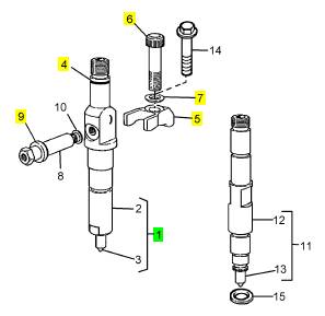
1 CV17009/1 Z 12 CV17009/1 Z 噴油器
4 ST10563 12 ST10563 密封O型圈
5 CV11597 12 CV11597 砂箱夾
6 CV18392 12 螺拴
7 CV1328 12 CV1328 墊圈
9 CV1494 12 CV1494 密封 -噴油器

項(xiàng)目 零配件號(hào)碼 最近的部分號(hào)碼 描述
2 CV17010 1 CV17009/1 Z 夾持工具
3 OD19115 1 OD19115 噴油器噴嘴
8 OD19060 1 OD19060 連接
10 OD18060 1 OD18060 墊圈

項(xiàng)目 零配件號(hào)碼 最近的部分號(hào)碼 描述
1 CV20524 2 CV20524 班卓琴螺拴
2 ST49938 6 ST49938 墊圈
3 CV20523 10 CV20523 班卓琴螺拴
4 ST49938 20 ST49938 墊圈
5 CV12984 1 CV12984 管 - 漏走開(kāi)
8 CV13906 1 CV13906 管 - 漏走開(kāi)
9 ST46004 2 ST46004 套筒
11 ST49432 1 ST49432 承接器
12 ST49851 1 ST49851 墊圈
13 CV1965 1 CV1965 夾
14 ST44436 1 ST44436 固定螺釘
15 ST44605 1 2318 A208 公制的螺帽
16 ST43160 1 2134 A008 墊圈
17 ST49432 1 ST49432 承接器
18 ST49851 1 ST49851 墊圈
19 CV9009 1 CV9009 連接
23 ST43502 2 ST43502 螺拴
24 ST43160 2 2134 A008 墊圈
25 ST49432 1 ST49432 承接器
26 ST49851 1 ST49851 墊圈
27 CV12870 1 CV12870 燃料管
28 ST46004 2 ST46004 套筒
29 ST46029 2 ST46029 螺帽
29 ST46029 2 ST46029 螺帽
30 ST11259 1 ST11259 肘管
31 ST11202 1 ST11202 螺帽
32 ST11227 1 ST11227 墊圈
33 CV12865 1 CV12865 管
34 CV7353 1 CV7353 夾
35 OD6039 1 OD6039 襯套
36 CV12990 1 CV12990 燃料管
39 ST49458 1 ST49458 承接器
40 ST49884 1 ST49851 墊圈
41 CV1615 1 OE9691 夾
42 OE9692 1 OE9692 襯套
43 ST46107 1 ST46107 肘管
44 CV12983 1 CV12983 燃料管
45 ST46007 2 ST46007 套筒
46 ST46032 2 ST46032 螺帽
47 ST11268 1 ST11268 肘管
48 ST11204 1 ST11204 螺帽
49 ST11229 1 ST11229 墊圈
50 CV12982 1 CV12982 燃料管
53 ST49449 1 ST49449 承接器
54 ST49853 1 ST49853 墊圈
55 CV11614 1 CV11614 承接器
56 0920113 2 0920113 墊圈
56 OD17531 2 0920113 墊圈
57 CV6843 1 CV6843 承接器
58 ST20528 1 ST20528 承接器
59 ST49853 1 ST49853 墊圈
60 OD14434 1 OD14434 閥
61 OD14433 1 OD14433 螺帽
62 OD3681 1 OD3681 班卓琴裝配
63 OD14432 1 OD14432 體
64 ST49891 1 ST49891 墊圈
65 ST46006 1 ST46006 套筒
66 ST46031 1 ST46031 螺帽
67 CV1595 2 CVK563 管
68 CV12718 1 CV12718 管
69 ST46004 2 ST46004 套筒
70 ST46029 2 ST46029 螺帽
71 ST46181 1 ST46181 TEEPIECE
72 ST46259 2 ST46259 異徑管接合器
73 ST46004 2 ST46004 套筒
74 ST46029 2 ST46029 螺帽

項(xiàng)目 零配件號(hào)碼 最近的部分號(hào)碼 描述
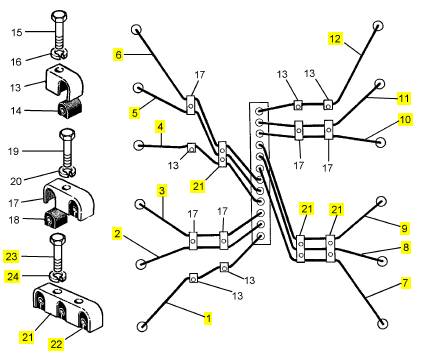
1 CV14591 1 CV14591 以管輸送 - 燃料 INJ 沒(méi)有 A1 CYL
2 CV14592 1 CV14592 以管輸送 - 燃料 INJ 沒(méi)有 A2 CYL
3 CV14593 1 CV14593 以管輸送 - 燃料 INJ 沒(méi)有 A3 CYL
4 CV14594 1 CV14594 以管輸送 - 燃料 INJ 沒(méi)有 A4 CYL
5 CV14595 1 CV14595 以管輸送 - 燃料 INJ 沒(méi)有 A5 CYL
6 CV14596 1 CV14596 以管輸送 - 燃料 INJ 沒(méi)有 A6 CYL
7 CV14597 1 CV14597 以管輸送 - 燃料 INJ 沒(méi)有 B1 CYL
8 CV14598 1 CV14598 以管輸送 - 燃料 INJ 沒(méi)有 B2 CYL
9 CV14599 1 CV14599 以管輸送 - 燃料 INJ 沒(méi)有 B3 CYL
10 CV14600 1 CV14600 以管輸送 - 燃料 INJ 沒(méi)有 B4 CYL
11 CV14601 1 CV14601 以管輸送 - 燃料 INJ 沒(méi)有 B5 CYL
12 CV14602 1 CV14602 以管輸送 - 燃料 INJ 沒(méi)有 B6 CYL
21 OD3634 8 OD3634 復(fù)緣
22 OD11048 24 OD11048 擋板
23 ST43502 16 ST43502 螺拴
24 2134 A008 16 2134 A008 墊圈

How to check the tappet clearances
The tappet clearance is measured between the
rocker levers and the top of the valve bridge pieces.
See page 45 for the size of the clearances.
Each valve bridge piece controls two valves. An
adjustment screw and lock nut is fitted to each bridge
piece to ensure that equal force is applied to both
valves from the rocker arm.
Before the tappet clearances are adjusted, the valve
bridge pieces MUST be checked and adjusted if
necessary.
Check and adjust the valve bridge pieces and tappet
clearances while the fuel injectors are removed for
service.
Caution: Numbers A1 and B1 cy linders are at the
front (fan end) of the engine.
1 Remove the air filters, the high pressure fuel pipes
and the fuel injector leak-off pipes.
2 Remov e the rocker covers .
3 Turn the crankshaft in the normal direction of
rotation until the inlet valve of number A1 cylinder has
just opened and the exhaust valve of the same
cylinder has not closed completely.
Check and, if neces sary, adjust the valve bridge
pieces of only the cylinder numbers which follow:
Inlet: A2, A4, A6, B1, B3, B5
Exhaust: A3, A5, A6, B1, B4, B5
To adjust the valve bridge pieces, proceed as follows:
Loosen the lock nut and the adjustment screw on the
relevant bridge piece. Use the rocker lever to apply
pressure to the bridge piece, then turn the adjustment
screw until it is just in contact with the tip of the valve
stem (A). Hold the adjustment screw in this position
with a screwdriver and tighten the lock nut to a torque
of 40 Nm (30 lbf ft). Use a torque wrench with a ring
spanner adaptor. Note that the reading on the torque
wrench must be adjusted to compensate for the extra
length caused by the ring spanner adaptor.
A
B
74
73
Check the tappet clearance AFTER the bridge
pieces hav e been adjusted. When the clearance
has been set correc tly (B), tighten the loc k nut to a
torque of 40 Nm (30 lbf ft).
4 Turn the crankshaft 360°, in the normal direction of
rotation until the inlet valves of number A6 cylinder
have just opened and the exhaus t valves of the same
cylinder have not closed completely. Check and, if
neces sary, adjust the valve bridge pieces of only the
cylinder numbers which follow:
Inlet: A1, A3, A5, B2, B4, B6
Exhaust: A1, A2, A4, B2, B3, B6
Check the tappet clearance AFTER the bridge
pieces hav e been adjusted. When the clearance
has been set correctly (B), tighten the loc k nut to a
torque of 40 Nm (30 lbf ft).
5 When all of the bridge pieces and tappet
clearances have been checked/adjusted, apply oil to
the rocker levers, the bridge pieces and the valve
springs. Fit the rocker covers, the fuel pipes and the
air filters.
28
This document has been printed from SPI². Not for Resale
Turbochargers
At the periods given in the service schedule,
How to clean the coolant system
The coolant s ystem must be drained and flushed
4
disconnect and remove the pipes from between the
air filters and the turbochargers. Turn, rapidly, the
rotor assembly of each turbocharger, check for
freedom of movement and for sounds of interference.
Deposits must not be removed from the turbine
wheels nor the compressor wheels or the balance of
the assemblies will be adversely affected.
Alternator
At the periods specified in the service schedule clean
the outside of the alternator and ensure that the
ventilation holes are clean. Contamination near to the
diodes can cause sparks and must be removed with
an approved cleaning fluid. A recommended fluid is
Electronic Cleaning Fluid, Grade 8-23, available in
aerosol containers or in larger quantities from Applied
Chemicals Limited, Uxbridge, Middlesex.
The alternator must be checked and corrected, if
necessary, by a person who has had the correc t
training, at the periods given in the service schedule.
How to drain the coolant system
Drain and flush the coolant system every 12 months
or less. The sys tem must be drained as soon as
possible after the engine is stopped and before any
deposits in the coolant have fallen to the bottom.
1 Ensure that the engine is level.
2 Carefully remove the header tank filler cap,
especially if the engine is hot.
Warning! Take care during removal of the filler cap
as the coolant sy stem will be under pressure.
3 Remove the coolant drain plugs from the front left
side and the rear right side of the engine. Ensure that
the drain holes are not restricted.
4 Flus h the s ystem with clean water.
5 Fit the engine and radiator drain plugs.
6 Fit a ‘coolant drained’ label if the coolant system is
not to be filled immediately.
through with clean water until it flows clear from all of
the drain taps.
If the sy stem has become contaminated, it must be
cleaned. Use clean water with 1% of Symperonic ‘N’.
This is equivalent to 10ml/litre or 45 ml/UK gallon.
1 Fill the system with clean water, at the same time
add the necessary amount of Symperonic ‘N’ at the
filler cap.
2 Operate the engine until the coolant reaches the
normal temperature of operation, then operate the
engine at maximum rated speed for 10 minutes.
Caution: In very cold ambient conditions, the
thermostat may not open to allow full circulation of the
c leaning fluid. If this occurs the engine must be
operated on load. The thermostat is open when the
pipe between the thermostat housing and the radiator
is hot. If the pipe is cool, the thermostat valve is
c losed.
3 Stop the engine and drain immediately the coolant
from all of the drain taps or plugs.
Warning! Take care during removal of the filler cap
as the c oolant sy stem will be under pressure.
4 Allow the engine to cool, then fill the system with
c lean water. Allow a minimum of 5 litres (1 UK gallon)
to drain from the system before the drain taps are
c losed.
5 Operate the engine as in operation 2, but maintain
maximum speed for 5 minutes only.
6 Repeat the operations in paragraphs 3, 4 and 5.
7 Drain the system completely and close the drain
taps. Fill the system with the correct coolant mixture.
How to fill the coolant system
Fill the system slowly, with the approved coolant
mixture, until the coolant is just in contact with the
bottom of the filler extension tube in the radiator.
Operate the engine until the coolant reaches the
normal temperature of operation. Stop the engine,
check the coolant level and, if necessary, add ex tra
coolant.
Warning! Take care during removal of the filler cap
as the coolant system will be under pressure.
29
This document has been printed from SPI². Not for Resale
This document has been printed from SPI². Not for Resale
5
Engine fluids
Diesel fuel
5
Diesel fuel must conform to the specifications given
below:
On highway
BS EN 590 1997 - max imum sulphur content 0.05%;
minimum cetane number 49 and minimum cetane
index 46.
Low sulphur fuels must conform to a lubricity
performance such that when tested using HFRR
(CEC F-06-A96) the wear s car meets a maximum of
460 microns.
Off highway
BS 2869: Part 2 1998 Class A2 - maximum sulphur
content 0.20%; minimum cetane number 45 and
minimum cetane index 45.
The use of fuels which do not conform to the above
standards can cause damage and/or reduced engine
life and could affect the warranty. Further details can
be obtained from the Service Department at Perkins
Engines Company Limited, Shrewsbury.
Coolant
Coolant mixture
The coolant approved for use in all diesel engines
manufactured by PE(S)L is a mixture of 50% inhibited
ethylene glycol, or inhibited propylene glycol, and
50% clean soft water.
Mixtures which contain methanol are NOT approved.
The corrosion inhibitor in the anti-freeze or coolant
concentrate, must be based on sodium nitrite, sodium
benzoate, sodium borate, sodium metasillicate and
benzotriazole.
Amines or phosphates must not be used. If operators
are in doubt, they should consult their source of supply.
In addition, all products which are used should
conform to BS 6580-1992.
For marine engines and engines which have
aluminium water-cooled exhaust manifolds, only
‘BASF 007/400F’ or Perkins anti-freeze are approved.
The Perkins anti-freeze, part numbers 21825 166 (1
litre) and 21825 167 (5 litre), can be obtained from the
Perkins worldwide distributor network.
Caution: Do NOT use salt water or any other coolant
which can cause corrosion in the closed coolant circuit.
Corrosion inhibitor
If anti-freeze is not available and is not required then
clean soft water, with 1% of PE(S)L corrosion
inhibitor, may be used. This ratio is equivalent to 0,5
litres of corrosion inhibitor to 50 litres (11 UK gallons)
of water. The corrosion inhibitor is available from the
Perkins worldwide distributor network, part number
21825 735 (1 litre). The use of this product should be
controlled in accordance with the manufacturer’s
instructions. For CHP (combined heat and power)
sets an alternative inhibitor, part number OE45765, is
recommended at a strength of 3%.
Water quality
Soft water means de-ionised water, distilled water,
rain water, or water from a mains supply which has a
maximum combined chloride and sulphate level of
150 mg/litre and a maximum total hardness of 250
mg/litre.
1 If soft water is not used, the cooling system may be
affected by the formation of hard deposits which can
cause the engine to overheat. This is especially
important for engines which have coolant added
frequently.
2 The use of products which are not approved for the
cooling system may cause serious problems. Coolant
mixtures with insufficient corrosion inhibitor can
cause erosion and/or corrosion of the cooling system
components.
31
This document has been printed from SPI². Not for Resale
5
Lubricating oil
1 Viscosity - Perkins Engines Company Limited
recommend the use of SAE15W/40 for all engines
that work in ambient temperatures above -15°C
(5°F). Below -15°C (5°F) and down to -20°C (-4°F)
the use of a 10W/30 oil is recommended. Down to -
30°C (-22°F) a 5W/40 fully synthetic oil is
recommended. For engines which operate in arc tic
conditions, below -30° C (-22°F), c ontact the Servic e
Department at Perkins Engines Company Limited,
Shrewsbury.
2 Performance Specification - For heavy duty
operation, base load, or extended drain (Eagle Tx
only), super high performance oils (SHPD) must be
used. These oils exceed the requirements of ACEA
E3 and are listed in the ‘preferred’ columns of the
table shown.
For light duty operation, oils which exceed the
requirements ACEA E2 may be used. These oils are
listed in the ‘a(chǎn)cceptable’ columns of the table shown.
It is recommended that the operator uses oils shown
in the ‘preferred’ columns as these give the greatest
protection.
32
This document has been printed from SPI². Not for Resale
5
Below is a list of oils recommended by Perkins Engines Company Limited, Shrewsbury. The operator must
ensure that the oil used conforms to the abov e requirements.
Recommended oils for Europe
|
Manufacturer of lubricating oil |
Preferred multi-grade oils which conform to ACEA E3 |
Acceptable multi-grade oils which conform to ACEA E2 |
|
AGIP |
Sigma Turbo 15W/40 Blitum T 15W/40 |
Universal Multifleet 15W/40 Master Super Turbo SHPD 15W/40 |
|
BP |
Vanellus C3 Extra 15W/40 Vanellus FE Extra10W/40 Vanellus HT 10W/40 Vanellus HT Ex tra 10W/40 |
Vanellus C3 Multi-grade 15W/40 |
|
CALTEX |
ONLY AVAILABLE IN FAR EAST, MIDDLE EAST, SOUTHERN AND EASTERN AFRICA AND AUSTRALASIA |
|
|
CASTROL |
Syntruck 5W/40 Dynamax 10W/40 Turbomax 15W/40 |
RX Super Plus 15W/40 |
|
CHEVRON |
Delo XLD 15W/40 Delo SHP 15W/40 |
Delo 500 15W/40 |
|
ELF |
Performance EXPERTY 10W/40 Performance TROPHY DX 15W/40 |
Performance Super D 15W/40 Performance 3D 15W/40 |
|
ESSO |
Essolube XTS 501 Essolube XT 401 |
Essolube XTS 301 Essolube XT 301 |
|
FINA |
Kappa First 5W/30 Kappa Extra 15W/40 Kappa Ultra 10W/40 |
Kappa Supra 15W/40 |
|
FUCHS |
Turbolene HPE 15W/40 Titan Unic Plus 10W/40 Titan Cargo MC 10W/40 |
Titan Formel Plus 15W/40 Turbolene D 15W/40 Turbolene D Plus 15W/40 |
|
KUWAIT |
Q8T 700 15W/40 Q8T 710 15W/40 Q8T 800 10W/40 |
Q8T 500 15W/40 |
|
MILLERS |
Multifleet XPD 15W/40 Truckmaster Global XD 15W/40 Truckmaster XHFE 10W/40 |
Maxifleet MP 15W/40 Suprex 15W/40 |
|
MOBIL |
Delvac 1 SHC 5W/40 Delvac XHP 15W/40 Delvac HP 15W/40 |
Delvac MX 15W/40 |
|
MORRIS |
XHD Plus 15W/40 XHD FE 10W/40 Ring Free Ultra 10W/40 |
Duplex CDX 15W/40 XHD 15W/40 |
|
SHELL |
Rimula Ultra 5W/30 Rimula Super 15W/40 |
Rimula X 15W/40 Rimula TX 15W/40 |
|
SUN |
Super HPD 15W/40 |
Forza 15W/40 |
|
TEXACO |
URSA Super TDX 10W/40 URSA Super TD 15W/40 |
URSA Super LA 15W/40 |
|
TOTAL |
Rubia TIR 8600 10W/40 Rubia TIR 6400 15W/40 |
Rubia 4400 15W/40 Rubia XT 15W/40 |
33
This document has been printed from SPI². Not for Resale
